<<< |
|
>>> |

|
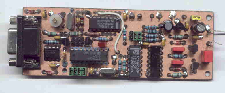
Here is a description of a simple Lowfer beacon transmitter. The transmitter crystal in my prototype is a third overtone 52.5 MHz unit that is run in fundamental mode. The CPU clock can be taken from the transmitter frequency divider if you want the keying to be synchronized to the carrier. Another option is to clock the divider from the CPU clock output pin instead. The output signal is a square wave with very fast rise time which means there are a lot of odd harmonics. The narrow bandwidth of a typical LF antenna will probably reduce radiation of unwanted harmonics to a sufficiently low level. However, the lower part of the antenna system, below the loading coil, may radiate too much harmonics. In this case, a lowpass filter must be used. The transmitter board shown above was used in the first SM / SM QSO on the 136 kHz band. With a supply voltage of around 27 volts I got about 4 watts of output power and managed to get a CW QSO with SM6PXJ who is located 120 km from my QTH. Not bad for two cheap TO-92 transistors! Another small longwave transmitter can be found on K0LR's
web page
|
||
| Schematic diagram: |

|
Component placement: |

|
Tracks on solder side (GIF file has 200 dpi resolution): |

|
Ground plane view (copper must be removed around marked holes): |

|
Source code for a simple CW beacon: Download PIC source code (easy_cw.zip, 4725 bytes) 73 de Johan SM6LKM |
||