
Design problem in the MEG circuitry
By Arend Lammertink, MScEE. July, 2024.
Contact: lamare at gmail dot com
I have recently been looking into the Motionless Energy Generator or MEG for short. The working principle is based on the principle also used in the electropermanent magnet:
https://en.wikipedia.org/wiki/Electropermanent_magnet
In this video, the ideas behind the MEG are explained by the inventors of the device:
http://www.youtube.com/watch?v=no50_5iSr2Y
In this video, it is said that higher frequencies would be required, so the first thing that comes to mind is to use ferrite cores, as has also been done by Jean Naudin in his version 2, judging by the text on his diagram:
As well as a photograph of the device:
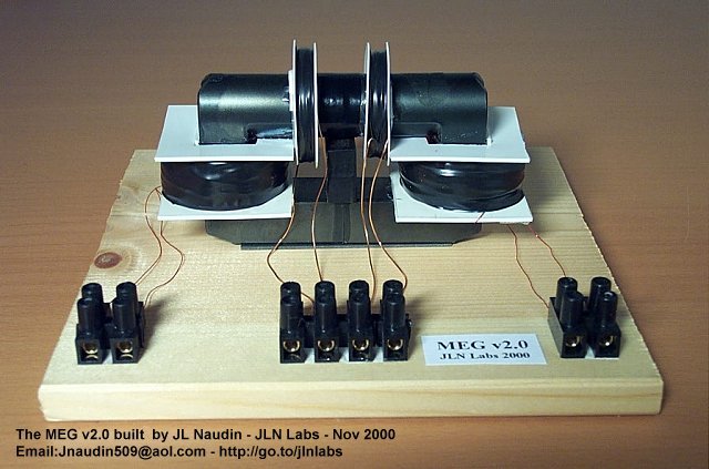
This version had a COP of 1.75, quite an accomplishment given the design flaw in his circuitry, which we will discuss below:
Freewheeling diodes
Let's take a look at Naudin's v1 schematic:
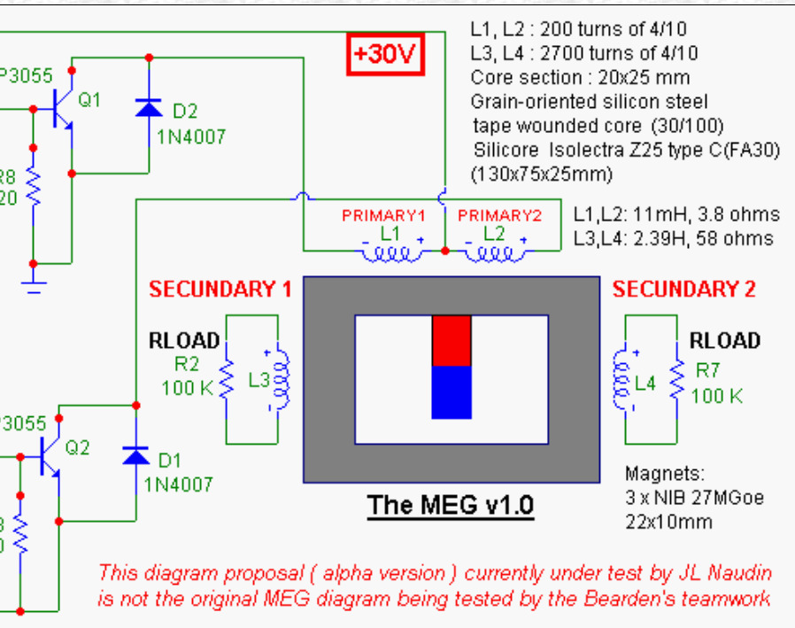
Notice the freewheeling diodes D1 and D2?
A freewheeling diode is used in inductive circuits to provide a path for the current when the driving voltage is suddenly reduced or removed. It prevents voltage spikes that can occur due to the inductive kickback, protecting the circuit components.
However, in this case this is not a good idea, because this way the coils get shortcutted and all the energy that is put in to energize the coil gets burned up by the diode and series resistance of the coil wire.
In the v2 schematic, these are still there, but integrated in the BUZ11 mosfets:
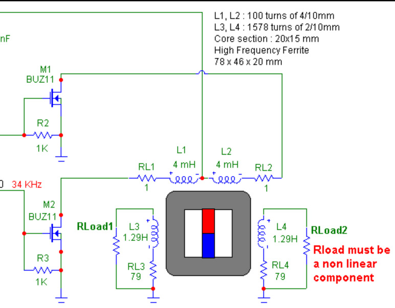
On the v2 page we read:
The new MEG control board v2.0 is now fully in line with the original Bearden's MEG comparing to my previous version.
So, apparently both Bearden's team as well as Naudin made this same mistake.
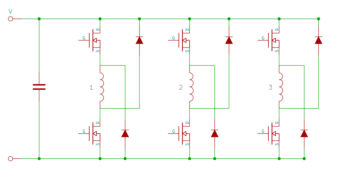
However, an elegant solution is to use an asymmetric bridge converter as described in my earlier article (optionally switching a number of BEMF recovery capacitors between series and parallel), with this picture showing a triple bridge converter:
https://en.wikipedia.org/wiki/Switched_reluctance_motor#Power_circuitry
Replication plan
Now that we found a mistake in the control circuitry, we can think about how to test a new control circuit, which requires a core. I made a drawing of how this could be done:
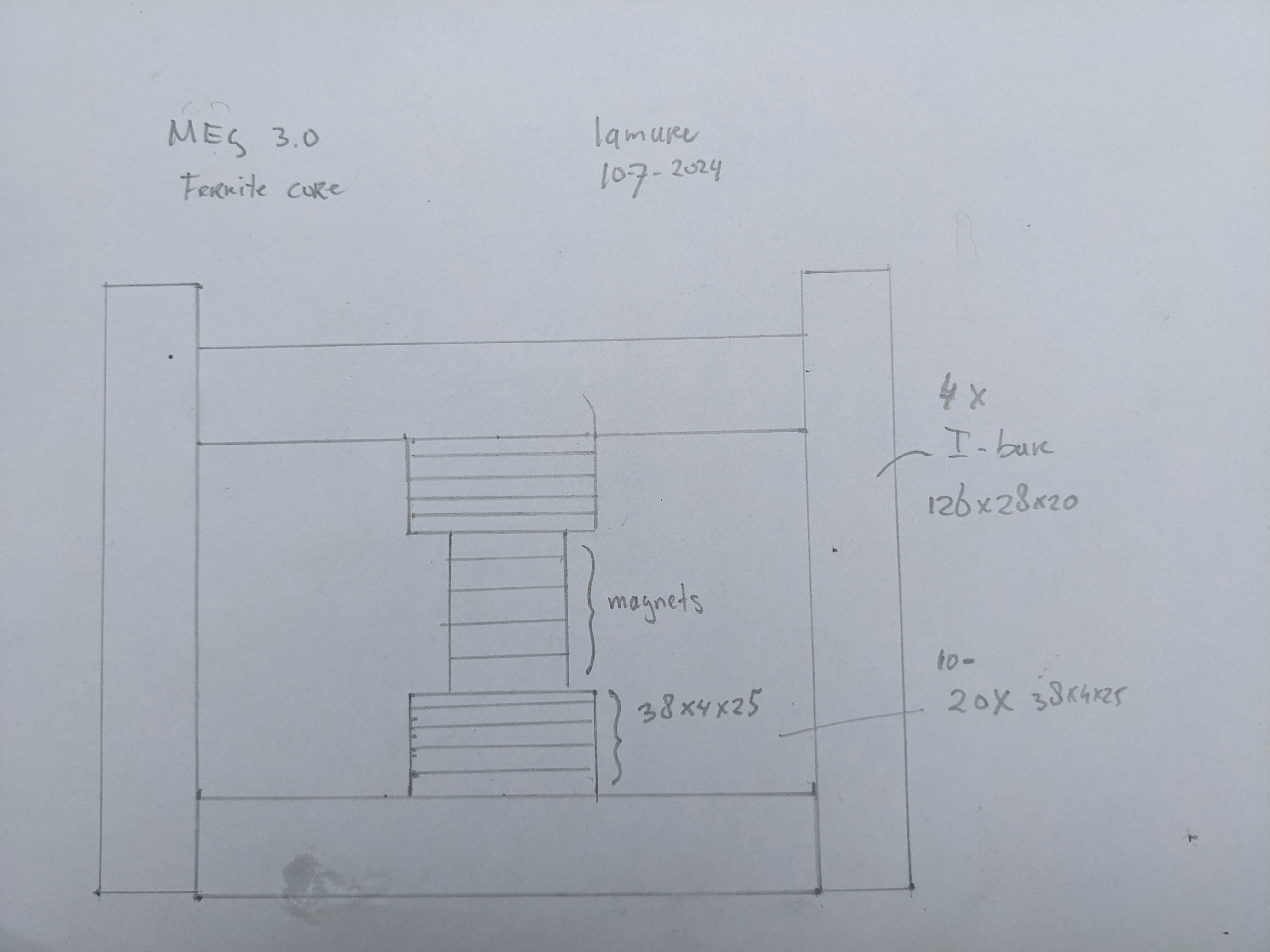
The idea is to use 4 126 x 28 x 20 I-bars for the main construction and up to 20 38 x 4 x 25 I-bars for the inner part with the magnet.
This has a big advantage, namely that this way we can play with the magnets and the core in the same was as shown in the video above. This way, it is possible to determine how many magnets would be needed to obtain the best results by varying the number of magnets and see how the core reacts.
Once that is determined, we can think about adding coils and a control circuit.
A little demo with the core (English subtitles):
http://www.youtube.com/watch?v=nWHmHftx3ao
In this demo, I used a neodymium magnet with a diameter of 17 mm. Using ChatGPT I now also have a method to estimate the diameter of magnet to use, which can be found in this Jupyter notebook:
https://github.com/l4m4re/notebooks/blob/main/MEG_stuff.ipynb
ChatGPT's conclusions:
Summary
- The flux density of 0.405 Tesla in the larger bars is within the allowable limit of 0.49 Tesla for N87 ferrite material.
- Your observation with a 17 mm diameter magnet confirms that the flux switching works without causing saturation.
You are on the right track with your experimentation. If you want to ensure even more margin, slightly reducing the magnet size or adjusting the configuration to distribute the flux more can help.
Controller design
Currently working on a new MEG controller design and pcb.
For the transistors, I've chosen the C3M0280090D, which can handle 11.5A up to 900V, after the design of Master Ivo who uses this series of mosfets in his experiments on his YouTube channel.
The current version of the schematic is available in KiCad format on my github, with the pdf version here:
https://github.com/l4m4re/BEMF_Controller/blob/main/kicad/MEG_controller.pdf
There's two projects in the KiCad folder, one being the "BEMF controller" that has now been abandoned, while the active project is "MEG controller".
Besides replacing the single mosfet with freewheel diode for an asymmetric bridge, also a major difference will be made with respect to the recovery coils. Rather than winding one recovery coil with a lot of windings the idea is to use multiple recovery coils in parallel with about the same number of windings as the control coils, since high voltages are not desirable and make it difficult to "close the loop" and get the thing self running, assuming the effect is actually there.
Finally, according to ChatGPT the switching of the flux on a ferrite core goes rather rapidly, in the order of several nanoseconds to about 1 microsecond, which means that the "on" time for the asymmetric bridge should be in the order of several nanoseconds to microseconds.
For the controller, I've chosen for the STM32 "black pill":
https://stm32world.com/wiki/Black_Pill
According to ChatGPT this processor is capable of achieving very short "on" times using a hardware timer:
"Thus, the minimal pulse width that can be achieved is approximately 11.9 ns for APB1 timers and 5.95 ns for APB2 timers, assuming the prescaler is set to 1 and the timer is operating at the maximum clock speed."
Further updates may become available at:
http://www.tuks.nl/wiki/index.php/Main/DesignProblemMEGCircuitry