
Radio Amateur Longitudinal Moon Bounce Challenge

By Arend Lammertink, MScEE. October, 2013.
In this article, I present a challenge to all radio amateurs on the planet. I will start with argueing that, contrary to popular belief, longitudinal dielectric "Tesla" waves do exist and propagate at a speed of sqrt(3) times the speed of light, supported by several experimental results published by various researchers over time. Now if these waves exist and have indeed been transmitted by people like Nikola Tesla, there is no reason why this could not be done by radio amateurs today. And if that is possible, why not attempt to do a moon-bounce with these kinds of waves?�
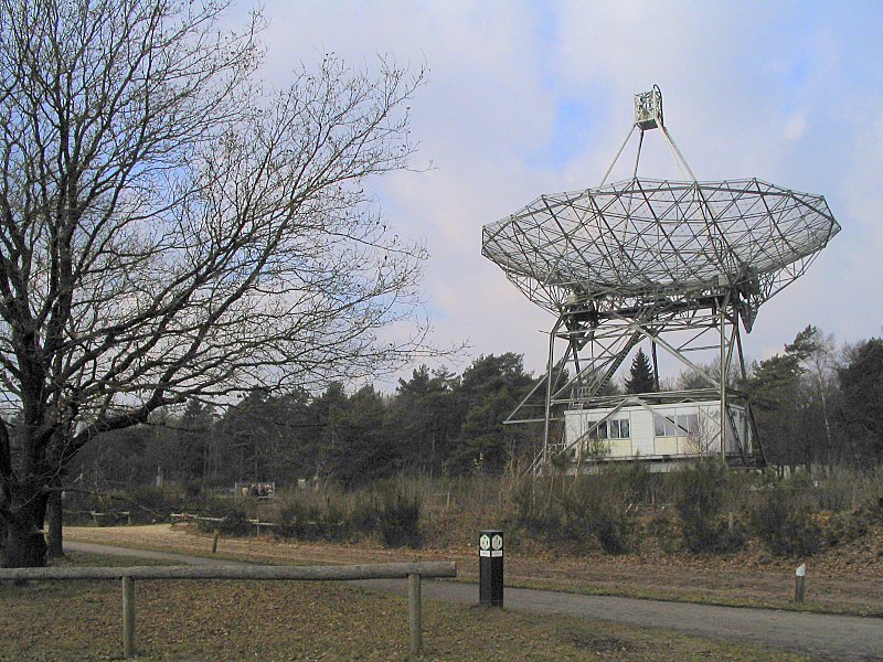
As it happens, in The Netherlands we have a beautiful instrument available which can be used for such an experiment. The Dwingeloo Radio Telescope, a 25 meter dish:�
� �
More about the history of this dish and how it came to be that this instrument is currently available for radio amateurs in this video (starting at about 2:00):
�
http://www.youtube.com/watch?v=TYYoRsPI5Es
In other words: we have a dish and we have a moon to reflect radio waves on. The only thing missing is an antenna system suitable for the transmission and reception of longitudinal dielectric waves...
So, which radio amateur is going to get his name in the history books for designing the antennas for the first longitudinal moon-bounce in history?
Do longitudinal faster-than-light waves exist?
To date, the vast majority of scientists and engineers would answer this question with a firm "No!", because Einstein's relativity theory predicts that it is impossible for any signal to propagate faster than the speed of light. It is taken for granted that this theory is correct and that the speed of light is constant across the Universe and virtually no one questions the validity of this theory, except a handful of dissidents such as myself. Needless to say, experimental proof of faster than light communication would rock the main stream scientific community, since it would prove beyond doubt that Einstein's famous theory is incorrect after all, as I theorized to be the case in 2011 based a/o on the excellent work of Dr. Charles Kenneth Thornhill.
However, having a dissident theory is one thing, having experimental evidence to support such a theory is another thing alltogether. Yet, such evidence does exist, ranging from experimental data from 1834 to the present time, including an article on "fast light" published in "Nature" in 2003 and data published by none less than Nikola Tesla. In other words: all we need is a "final blow" to show the world that Tesla got it right all these years after all.
Charles Wheatstone
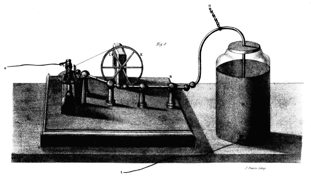
The oldest data to my knowledge which suggests faster than light signal propagation is possible dates from 1834, when Sir Charles Wheatstone published "An Account of some Experiments to measure the Velocity of Electricity and the Duration of Electric Light".�
[...]
A very interesting detail is how he measured the rotation speed of his mirror:
Fizeau and Foucault based their apparatus on Wheatstone's:
Faucoult was even more accurate:�
So, how come that with essentially the same measuring method, one just gets "an interesting approximation" being more than 50% off, while the other comes within 1% of the actual value?
Let's do some calculations, based on the hypothesis that what Wheatstone acually measured, might have been a longitudinal dielectric wave instead of a transverse electromagnetic wave, the kinds of waves which normally propagate along our antennas.
The first question to answer would be the question of how fast such a longitudinal dielectric wave would propagate. In the literature, �a relation between the propagation speeds of longitudinal versus transverse phenomena, the Poisson ratio, is described, which is the ratio of transverse contraction strain to longitudinal extension strain in the direction of stretching force. This has a theoretic value between -1 and 0.5. This article is more specific:
This means that if the medium, the aether, can be considered to be a perfectly isotropic elastic material, we would get a propagation speed for longitudinal waves of 1.73 (sqrt(3)) times the speed of a transverse wave trough the same medium, wich would be sqrt(3) times c in vacuum.
However, the propagation speed of electromagnetic waves around an antenna is less than the speed of light. We all know that when designing an antenna, we need to take a propagation factor of about 0.93 into account. So, if longitudinal wave phenomena exist which are capable of propagating along a wire with a velocity factor of 0.93, we would expect a propagation speed of about 1.73 �* 0.93 * �186,282 = 299,709 miles per second.�
This would mean that Wheatstone's measurement would be less than 4% off the expected value, a very reasonable result considering the margins of error achieved by Fizeau and Foucault who used essentially the same measuring technique, albeit to measure a different kind of signal. Considering this, it would definitely be interesting to repeat Wheatstone's experiment with modern equipment to see whether or not his 50% off actually was "a measuring error" or, in hindsight, should be regarded to be the first accurate measurement of the propagation speed of longitudinal dielectric waves.
Nikola Tesla
The next data comes from none less than Nikola Tesla, who basically invented the 20th century but somehow appears to have been mostly forgotten despite his numerous inventions involving electricity, including radio. For example, let's take a look at Wikipedia's page on the invention of radio:
How come we don't find Tesla in this list of names? After all, in 1943 the U.S. Supreme Court upheld Tesla's radio patent number 645,576 over Marconi's according to PBS:
[...]
In the MARCONI WIRELESS T. CO. OF AMERICA v. U.S., 320 U.S. 1 (1943) case, the US Supreme Court stated:
In Novevember, 1931 Hugo Gernsback described Tesla's view on a/o the propagation of radio signals in his Faster Than Light! article:
The fundamental distinction between Tesla's wireless power system and our current, electromagnetic based, radio technologies is that Tesla used electrostatic induction instead of electrodynamic induction:
Now consider the fact that Tesla was able to light electric lamps at a distance of three miles in 1893 using electrostatic induction and realize how difficult it is to do the same thing with electromagnetic induction, as NASA demonstrated in their Goldstone RADAR experiment from 1975:
�
http://www.youtube.com/watch?v=aeo1UXXPcxY
So, while Tesla demonstrated in the late 1800s what can be done with electrostatic induction, this has all but been forgotten and there are virtually no practical applications of this powerfull wireless technology to be found on the planet anymore. The NASA demonstration is a typical illustration of the fact that no one even considers using electrostatic induction over electromagnetics these days.
Now let's continue with Gernsback:
In Tesla's own words:
As we saw, electrostatic induction is the key into understanding Tesla's technology. The electric field, or dielectric field, is governed by Coulomb's law:
http://en.wikipedia.org/wiki/Coulomb's_law
Coulomb's law or Coulomb's inverse-square law is a law of physics describing the electrostatic interaction between electrically charged particles. This law was first published in 1785 by French physicist Charles Augustin de Coulomb and was essential to the development of the theory of electromagnetism. It is analogous to Newton's inverse-square law of universal gravitation. Coulomb's law can be used to derive Gauss's law, and vice versa. Coulomb's law has been tested heavily and all observations are consistent with the law.
[...]
The magnitude of the electric field �can be derived from Coulomb's law. By choosing one of the point charges to be the source, and the other to be the test charge, it follows from Coulomb's law that the magnitude of the electric field �created by a single source point charge �at a certain distance from it �in vacuum is given by ....
So, it is a well established scientific fact that the static electric field can propagate trough the vacuum. However, even though longitudinal dielectric waves are nothing but periodic variations of the electric field strength, these supposedly cannot propagate trough the vacuum because there are no free charge carriers in the vacuum.
http://en.wikipedia.org/wiki/Longitudinal_wave
Electromagnetic[edit]
Maxwell's equations lead to the prediction of electromagnetic waves in a vacuum, which are transverse (in that the electric fields and magnetic fields vary perpendicularly to the direction of propagation).[2] However, waves can exist in plasmas or confined spaces, called plasma waves, which can be longitudinal, transverse, or a mixture of both.[2][3] Plasma waves can also occur in force-free magnetic fields[citation needed]. In the early development of electromagnetism, there were some like Alexandru Proca (1897-1955) known for developing relativistic quantum field equations bearing his name (Proca's equations) for the massive, vector spin-1 mesons. In recent decades some extended electromagnetic theorists, such as Jean-Pierre Vigier and Bo Lehnert of the Swedish Royal Society, have used the Proca equation in an attempt to demonstrate photon mass [4] as a longitudinal electromagnetic component of Maxwell's equations, suggesting that longitudinal electromagnetic waves could exist in a Dirac polarized vacuum. After Heaviside's attempts to generalize Maxwell's equations, Heaviside came to the conclusion that electromagnetic waves were not to be found as longitudinal waves in "free space" or homogeneous media.[5] But Maxwell's equations do lead to the appearance of longitudinal waves under some circumstances, for example, in plasma waves or guided waves. Basically distinct from the "free-space" waves, such as those studied by Hertz in his UHF experiments, are Zenneck waves.[6] The longitudinal modes of a resonant cavity are the particular standing wave patterns formed by waves confined in a cavity. The longitudinal modes correspond to those wavelengths of the wave which are reinforced by constructive interference after many reflections from the cavity's reflecting surfaces. Recently, Haifeng Wang et al. proposed a method that can generate a longitudinal electromagnetic (light) wave in free space, and this wave can propagate without divergence for a few wavelengths.[7]
http://www.nature.com/nphoton/journal/v2/n8/full/nphoton.2008.127.html
Creation of a needle of longitudinally polarized light in vacuum using binary optics
Haifeng Wang1, Luping Shi1, Boris Lukyanchuk1, Colin Sheppard3 & Chong Tow Chong1,2
Abstract Recently many ideas have been proposed for the use of a longitudinal field for particle acceleration, fluorescent imaging, second-harmonic generation and Raman spectroscopy. A few methods to enhance the longitudinal field component have been suggested, but all have insufficient optical efficiency and non-uniform axial field strength. Here we report a new method that permits the combination of very unusual properties of light in the focal region, permitting the creation of a 'pure' longitudinal light beam with subdiffraction beam size (0.43). This beam is non-diffracting; that is, it propagates without divergence over a long distance (of about 4) in free space. This is achieved by focusing a radially polarized Bessel�Gaussian beam with a combination of a binary-phase optical element and a high-numerical-aperture lens. This binary optics works as a special polarization filter enhancing the longitudinal component.
http://en.wikipedia.org/wiki/Plasma_waves
Waves in plasmas can be classified as electromagnetic or electrostatic according to whether or not there is an oscillating magnetic field. Applying Faraday's law of induction to plane waves, we find , implying that an electrostatic wave must be purely longitudinal. An electromagnetic wave, in contrast, must have a transverse component, but may also be partially longitudinal.
Eric Dollard (N6KPH)
Maar Eric Dollard heeft in de jaren 80 het e.e.a. van Tesla gerepliceerd en daar zijn video�s van:
http://vimeo.com/11917342 http://vimeo.com/12721160
Dollard bepaalt de propagatiesnelheid van longitudinale golven langs een coax kabel, waarbij de propagatiesnelheid vanwege het aanwezig zijn van het dielectricum in de kern voor beide soorten golven iets van 80% van die in vacuum of zo is, door middel van het meten van de resonantiefrequentie in de veschillende modes. Dit is ook beschreven in NASA�s �Advanced Energetics for Aeronautical Applications: Volume II� :
http://www.tuks.nl/pdf/Reference_Material/NASA%20Advanced%20Energetics%20for%20Aeronautical%20Applications%20-%20 VOL%20II.pdf
-:- The fundamental differences between �longitudinal electric waves� and what are commonly referred to as �electromagnetic waves� were first described by the inventor Dr. Nikola Tesla and the mathematician Dr. Charles P. Steinmetz approximately 100 years ago (Refs. 21 and 22).
Dr. Nikola Tesla invented the ac electric transmission system and its major components during the 1880s. At approximately 1890, Dr. Tesla began to investigate, write about, and demonstrate electric and electric transmission phenomena, which appeared unusual at that time and are very difficult to theoretically describe now based upon contemporary electric theory (Ref. 23). Over the years, investigators have claimed that Dr. Tesla was using a type of electric transmission referred to as longitudinal electric waves. It is to be understood that this claim (longitudinal electric waves) is applicable for the Tesla experimental phenomena replicated in the 1980s by a group of researchers in southern California who call themselves the Borderland Sciences Research Foundation (BSRF) (Refs. 17 and 24). These replications are described subsequently.
[...]
The BSRF researchers claimed that they have demonstrated that the wave propagation velocities of transverse waves and longitudinal waves are significantly different, even when they are produced by the same signal source.
The wave velocity of transverse waves was determined by measuring the frequency for which low-power radio waves directly coupled to the end of a conductor of known length produced a resonance condition that resulted in a maximum voltage measured at the �far� (nonsource) end of the conductor. Wave velocity was calculated as (resonant) frequency times wave length, which was equal to frequency times conductor length times four. (The factor of four is included because reflected energy and input energy result in a maximum output when the conductor length is one-quarter of the full [electric] wave length.) The wave velocity of longitudinal waves was determined in a very similar manner; however, the radio waves were capacitively (i.e., not directly) coupled to one end of a conductor equal in length to the conductor used for the transverse wave velocity measurement. As was done for transverse waves, wave velocity was calculated as (resonant) frequency times conductor length times four.
The results of these determinations were as follows:
� transverse wave velocity = 2.44 x 10⁸ m/s = 0.81 x c; and � longitudinal wave velocity = 3.74 x 10⁸ m/s = 1.25 x c.
The velocity of transverse waves in �free space� (i.e., not confined to a conductor or other physical material) has been measured to be 3.00 x 10⁸ m/s, and this value is commonly referred to as �the velocity of light, c� (Ref. 25). -:-
Merk op dat de verhouding 1.25/0.81 = 1.54 dicht in de buurt zit van de theoretische 1.57.
Dollard claimt zelf ook een vergelijkbaar systeem gebouwd te hebben, zijn �Telluric system�, gebaseerd op het antenne systeem van Alexanderson:
http://www.tuks.nl/wiki/index.php/Main/TelluricElectricWaves
-:- It took me 8 years until I finished �Symbolic Representation of the Generalized Electric Wave�. However note that the space versor part is not there , it is at the end of “Theory of Wireless Power�. Fortunately The Dumpsters or Olin Bales of SwinePlanet did not get these. They were 8 years of hard work every day on my part.
The entire working Telluric system WAS working at Landers. There WAS your velocity greater than c. It was based upon a navy situation of transmitting direct to deep submerged submarines through water, and through the metal hull of the sub.
Anyway the Mojave Research Facility at 57474 Linn Road Landers, is in the hands of criminals. Our Navy is N.F.G. now. -:-
Meer info hier over: http://www.tuks.nl/pdf/Eric_Dollard_Document_Collection/Build_YO_Alexanderson_System/
Wesley Monstein
Adolph & Erich Erdmann
Perhaps the most concrete design I found which could be built upon is the design by the Erdmann brothers, which would have to be scaled down for the 23cm band:
http://www.tuks.nl/pdf/Reference_Material/Fast_Light/Erdmann%20-%20Faster%20than%20Light,%20the%20Revolutionary%20Radio%20Antenna%20that%20Conquers%20Space.pdf http://www.tuks.nl/pdf/Reference_Material/Fast_Light/Erdmann%20-%20Experiments%20with%20Faster%20than%20Light%20Receiving%20Antenna.pdf http://www.tuks.nl/pdf/Reference_Material/Fast_Light/Erdmann%20-%20Faster%20Than%20Light%20Speed%20Two-Way%20Radio%20Communications%20Antenna%20%20-%20CA2469325A1.pdf http://www.tuks.nl/pdf/Reference_Material/Fast_Light/Erdmann%20-%20Underwater%20magnetic%20field%20communication%20system%20-CA2441882A1.pdf
Some more referenence material on "faster than light" phenomena: http://www.tuks.nl/pdf/Reference_Material/Fast_Light/
Paul Stowe
http://www.tuks.nl/wiki/index.php/Main/QuestioningQuantumMechanics
What I see in Stowe's work is the idea of defining an ideal super-fluid in terms of Newtonian physics and then working out how this connects a/o electro-magnetism and gravity. Now I am an electrical engineer and have studied a/o the work of Eric Dollard and various free energy systems, most notably the car on water by Stan Meyer. One of the most intriguing theoretic controversy that came forward is the question whether or not longitudinal electric waves can propagate trough the vacuum. This is claimed to be the case by Eric Dollard and I believe this to be true.
What I see wrong with the current EM model of main stream science is that it sees "charge carriers" as being the cause for EM fields to exist, while charge carriers are particles, which are also waves according to the wave-particle duality principle. Now supposedly EM waves can propagate trough the vacuum, because they are particles, but longitudinal waves cannot, because they supposedly need free charge carriers to be present in order to be able to propagate. To me, it is clear that a deeper cause must be present for EM waves to exist, and that is why I am a proponent of an aether theory.
One problem that comes forth is that longitudinal waves are pure pressure waves and do not have a magnetic component. Now you need some kind of momentum in order to be able to propagate a wave, which in the normal EM case is the magnetic component. For the longitudinal case, we have no concept for the momentum part. Now when you go to the aether concept of Stowe, you have a super fluid, wherein the magnetic field is defined as the rotation of the fluid. So, within current EM theory, only the rotational part of the aether momentum is modelled. The non-rotational part, which is also present, is totally ignored. With Stowe's version, we do not have that problem and thus have a foundation for extending the current understanding of the EM field, such that longitudinal waves can be described.
Then, his statement that "gravity = Grad E" is also intriguing, because it offers an understanding of the experiments conducted by T.T. Brown. By integrating gravity into the model like this, we get a complete aether theory, which also resolves the problem around whether or not we have an "entrained" aether or not. (see Cantrell: http://www.infinite-energy.com/iemagazine/issue59/adissidentview.html ).
So, to me, conceptually Stowe's theory solves a lot of problems we have with current EM theory, because the wave-particle duality principle all but demands gravity to be an integral part of EM theory. There may be many rough edges and many refinements may be needed, but to me the conceptual foundation appears to be rock-solid.
Recent main stream view on "faster than light" phenomena
Th�venaz
Stenner et al
http://en.wikipedia.org/wiki/Dispersion_%28optics%29
When we take a look at the WikiPedia page on group velocity, we find a picture which shows the group velocity as the velocity of the signal as in an AM modulated signal on a carrier wave:
Not that in this picture, the "carrier wave" moves from right to left, and the "AM" signal from left to right. So, this is what a negative group velocity would like of we were capable of creating such a signal with radio waves, which would require heterodyning of a number of (carrier) waves.
Now let's continue with the optical dispersion page:

So, according to the main stream interpretation, under certain conditions having to do with "resonance" (and thus "heterodyning") an anomaly occurs, which is called "anomalous dispersion".�
Now let's get this straight. The anomaly is that we get a negative group velocity, which supposedly is no longer an indicator of signal velocity, but it is an accepted fact that it is possible to create a situation whereby the group velocity exceeds c or becomes negative. Now when the group velocity becomes negative, we get something which is considered to be very strange: "a pulse can appear to exit a medium before it enters".�
In other words: when we get a negative group velocity, which would normally considered to be the signal velocity, we get the situation that what normally would be considered "the signal" appears FIRST at "the exit" of the medium and some time later at the "entrance" of the medium, which is what you would "normally" expect IF you would consider the group velocity to be equal to the signal velocity. You see, IF the signal velocity equals the negative group velocity, well, then the signal would go the other way as your carrier wave and thus appears FIRST at the "exit" and LATER at the "entrance". Sesame Street level logic, I should think.
So, the anomaly is that signals, when considered along "normal" Sesame Street level logic, can be experimentally shown to propagate FASTER than the speed of light. And THAT is a problem, because according to Einstein's theory, that is impossible. So, what to do? Announce to the world that you have experimental proof that Einstein's theory is incorrect?
Dit is toch wel erg fascinerend. Een puls kan sneller dan het licht propageren (of zelfs een negatieve snelheid hebben), maar een signaal niet. Waarin verschilt een puls nu dan wel van een signaal?
http://scienceblog.com/light.html
http://tuks.nl/Mirror/ScienceBlog/light.html
Juist. Niets aan de hand. Nothing to see here. Slechts een gedeelte van het signaal gaat sneller dan c. Maar welk gedeelte dan?
Juist. Het gaat om een gedeelte van het signaal, waarbij er sprake is van een beperkte bandbreedte waarbinnen sneller dan licht propagatie mogelijk is.
Wikipedia nog eens:
Dat is interessant. Er is dus een specifieke, medium afhankelijke, resonantie frequentie waarbij sneller dan licht propagatie optreedt, precies zoals ik betoogd heb dat dit ook in het RF geval optreedt bij antennes. En wat ik daar ook bij betoogd heb, is dat het erg lastig is om longitudinale golven te meten. En dat is ook precies waar men hier tegen aan loopt:
Scienceblog:
Dit is een paper van Th�venaz dat wellicht meer details geeft:
http://infoscience.epfl.ch/record/161515/files/04598375.pdf
Bijzonder interessant. Het mechanisme waar het om lijkt te draaien heet Brillouin scattering: http://en.wikipedia.org/wiki/Brillouin_scattering
Merk op dat het hier gaat om een mechanische compressie van het medium, en voor zover me nu duidelijk is wordt dit gedaan met behulp van geluidsgolven.
Uit het artikel in mijn vorige post:�
Interessant detail is dat het hier gaat om silica. Dit is natuurlijk gewoon glas, maar het is wel een silicium oxide en silicium is een halfgeleider. En wat hier gebruikt wordt is de kristallijne vorm:
http://nl.wikipedia.org/wiki/Siliciumdioxide
"Silicium(di)oxide of silica is het bekendste oxide van silicium. In de natuur komt het in diverse vormen voor, zowel in kristallijne als niet-kristallijne (amorfe) vorm. Kwarts is een voorbeeld van kristallijn silica, andere voorbeelden zijn cristobaliet en tridymiet. Opaal is een voorbeeld van amorf silica net als door extreme hitte samengesmolten kwarts (kwartsglas)."
Het artikel van Stenner �The speed of information in a �fast-light� optical medium� over group velocity, etc. kan hier gevonden worden:
http://www.phy.duke.edu/research/photon/qelectron/pubs/StennerNatureFastLight.pdf
�Maar iedere keer als ik die links zelf bekijk, zie ik al redelijk snel dat ze niet datgene beweren wat jij er in denkt te lezen.��
Ok. Ben soms misschien even wat te enthousiast over deze boeiende materie. Ik had overigens bij mijn weten nog geen conclusies getrokken. En aldus hebben we dan een opmerkelijke schending van causaliteit. Je zegt hier in feite dat jij nu in staat bent te concluderen dat er niet staat wat ik denk te lezen, terwijl ik nog geen conclusies gepost heb en je kortom op dit moment niet over informatie beschikt op grond waarvan jij zou kunnen concluderen dat ik iets heb gelezen dat er niet staat. ^_^�
Maar zonder gekheid, ik waardeer het dat jullie bereid zijn de discussie aan te gaan. Dat is wat echte wetenschappers doen, elkaar een beetje intellectueel uitdagen en uiteindelijk tot conclusies komen, zodat de wetenschap weer een stapje verder komt ten dienste van ons allemaal.�
En zoals Einstein al zei: �Question everything�. Als wij als wetenschappers beweringen van collega wetenschappers en tijdschriften klakkeloos voor waar aan nemen, dan kan de wetenschap niet werken. Op dit moment kun je m.i. toch duidelijk een bijzondere vooringenomenheid waarnemen, waarbij het uiten van kritiek op de relativiteitstheorie, hoe goed onderbouwd ook, zo ongeveer ervaren wordt als Godslastering.�
Met andere woorden: de relativiteitstheorie wordt zo ongeveer verdedigd als zijnde een religie en dat is hoe dan ook niet gezond.�
Een heel klein voorbeeld van hoe het er nu echt bij staat bij de gevestigde tijdschriften is dit stukje uit het abstract van het artikel van Stenner, nota bene in Nature:�
Nu is de group velocity v_g dus de snelheid van de omhullende van een zich voortplantend signaal, waar normaal gesproken de informatie in zit. Wikipedia heeft een leuk plaatje met een animatie waarbij de groep snelheid negatief is ten opzichte van de fase snelheid, de draaggolf: http://en.wikipedia.org/wiki/Group_velocity
De draaggolf (fase snelheid) beweegt naar links, de omhullende (groep snelheid) beweegt naar rechts. En nu krijgt Nature het dus voor elkaar een artikel te publiceren waarin beweerd wordt dat een negatieve groepssnelheid een schending van causaliteit zou zijn. Want het signaal bevindt zich eerder op de �uitgang� dan op de �ingang�.�
Dit zijn toch gewoon denkfouten van Sesamstraat niveau?�
Ik bedoel: als de omhullende de andere kant op beweegt dan de draaggolf, dan gaat die omhullende toch gewoon van de andere kant je glasvezel IN en komt er aldus enige tijd later weer UIT en wel aan de kant die je vanuit de draaggolf als INgang ziet. Maar het ding beweegt dus gewoon achteruit t.o.v. de voortbeweging van de draaggolf en dus bevindt hij zich eerst op het einde dat je vanuit de draaggolf gezien als uitgang bestempelt en pas later op het einde dat je vanuit de draaggolf bezien als ingang bestempelt�
Het artikel van Th�venaz bevat een interessant detail:
Wederom, dezelfde denkfout, maar dat terzijde.
BTW: men verwijst naar dit artikel voor meer detail:� http://infoscience.epfl.ch/record/128303/files/ApplPhysLett_87_081113.pdf
Maar goed, waar het om gaat is dat we hier een maximale snelheidsfactor zien van 1.44, vrij dicht bij de eerder genoemde pi/2 voor het geval van longitudinale dielectrische (ofwel electro�statische�) LD golven.
Nu is de vraag uiteindelijk wat de aard van die omhullende golf is. Is dit nu inderdaad een longitudinale dielectrische golf, of is het toch iets anders?
OK. Nu heb ik betoogd dat er bij een dipool met een lengte van pi/2 keer 1/2 lambda iets bijzonders aan de hand is. Omdat er sprake is van golf reflecties op de uiteinden van de dipool, krijg je dus een staande golf, waarbij de totale rondgaande faseverschuiving van het EM veld 90 graden is.
Dit is echter niet het hele verhaal. Het elektrische veld is gerelateerd aan spanningen en het magnetische veld is gerelateerd aan het lopen van stroom. Nu heb je aan het uiteinde van een antenne dus de situatie dat er geen stroom kan lopen, maar de spanning vrij kan varieren.
Met andere woorden: voor het E-veld is het uiteinde van een antenne open, maar voor het magnetische veld is deze gesloten.
En dat betekent dat je voor beide componenten van de golf een andere faseverschuiving krijgt op de uiteinden van de dipool, net als bij een open/gesloten einde bij een touwtje dat je laat slingeren:
http://electron9.phys.utk.edu/phys136d/modules/m9/film.htm
http://labman.phys.utk.edu/phys222/modules/m9/Thin%20films.htm
http://www.tuks.nl/Mirror/labman.phys.utk.edu/Thin%20films.htm
We hebben hier dus de eigenaardige situatie dat de ene component van het veld geinverteerd gereflecteerd wordt op het uiteinde van de dipool (het B-veld) en het andere niet (het E-veld).
Als we de metingen van Dollard e.a. mogen geloven, dan zou je verwachten dat als je deze situatie analytisch gaat uitwerken, je een significant verschil zult zien in de resulterende E-veldsterkte en de B-veldsterkte in vergelijking met de situatie waarbij je een dipool met een lengte van 1/2 lambda neemt. En je zou daarnaast verwachten een groepssnelheid te vinden van pi/2 keer c�
Possible designs
Terman's book:
Aha!
Now what if we want this phase velocity, the "apparent velocity in the guide" to be pi/2 times c, the (postulated) propagation speed of longitudinal dielectric waves?
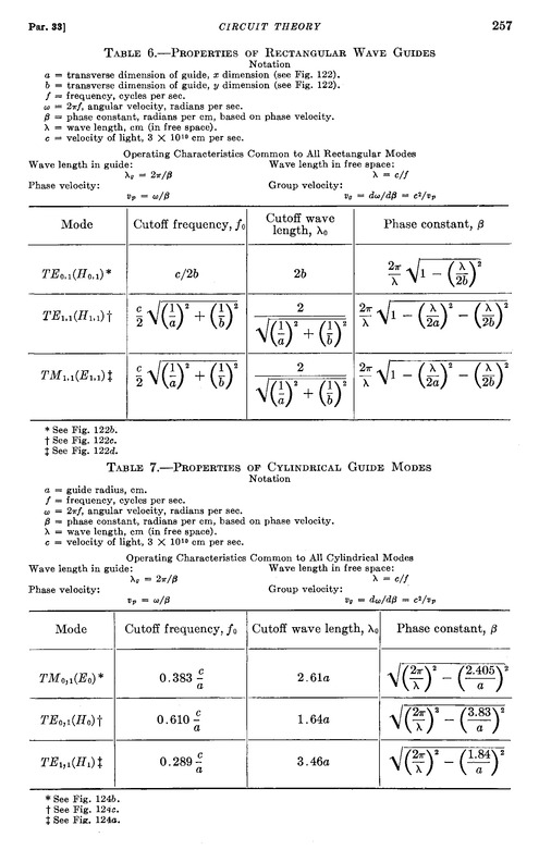
In table 7, some properties of different propagation modes are given for circular waveguides, the only type of waveguides that support the TM_0,1 mode.
It says a/o: lambda_g = 2 pi / beta. And we want this wavelength to be equal to pi/2 times the wavelength in free space, or:
2 pi / beta = pi/2 * lambda.
This requires beta to be equal to 4 / lambda.
From table 7, we can see the formula for beta as a function of lambda and a, a/o for the TM_0,1 mode, which we take equal to 4 / lambda.
When we work that out, we get:
a = SQRT ( 2,405^2 / ( 4 pi^2 - 16 ) ) * lambda,
which computes to:
a = 0.4963416 * lambda.
(note that a denotes the *radius* of the waveguide, not the diameter)
In other words: if we take a circular waveguide with a diameter equal to the free space wavelength lambda, we get an "apparent" group velocity of pi/2 times c within our waveguide, all according to accepted theory, literally "by the book"
For this diameter, only two propagation modes are possible, namely the TM_0,1 and the TE_1,1 mode.
In this image, you can see the fundamental difference between TE and TM modes, although this is definitely not the TM_0,1 mode, since that is not supported by rectangular waveguides:
http://www.allaboutcircuits.com/vol_2/chpt_14/8.html
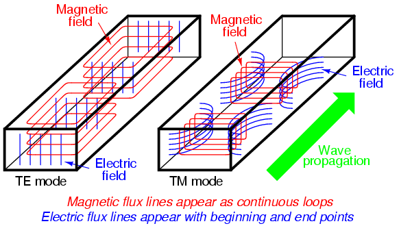
If you look at the magnetic lines and remember the right hand rule, it is clear that the "current", or aether movement, is in the other direction:

With a TE mode, we get "up and down" "current" or "movement of the aether", while with the TM mode, we get movements along the length direction of the wave guide.
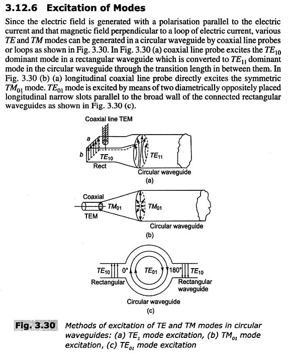
So, it seems like all we need to do is figure out how this TM_0,1 mode can best be excited. Yes, Terman gives some hints, but so far I have not been able to find any detailed information.
In other news, the dish in Dwingeloo has been restored and looks as good as new:

I put the formulas from table 7 into a spreadsheet, which you can find here: http://www.tuks.nl/Spice/TM_01_Mode_Cantenna/Lamare_waveguide_calc.xls
I calculated the dimensions using a velocity factor of 0.92, which was obtained by simulating a 1/4 wave whip antenna (the probe). The calculated length for the whip was 5.783 cm (calculating with c=299792458 m/s), while the optimal length as simulated was 5.336 cm.
The calculated (and simulated) length of the waveguide is 27.7 cm for the design frequency of 1296 MHz. Furthermore, for calculating the desired group wavelength, I calculated with a propagation speed of sqrt(3) * c for the propagation speed of longitudinal waves, instead of the pi/2 * c I used earlier, because of the theoretical basis for that (see post quoted above).
Some more on this velocity factor in this post:
http://www.energeticforum.com/166020-post37.html
Update:
Some documentation I used: http://www.tuks.nl/pdf/Reference_Material/TM_mode_waveguide/
I made some screenshots of the simulation results. First of all, a 3D view of the antenna:
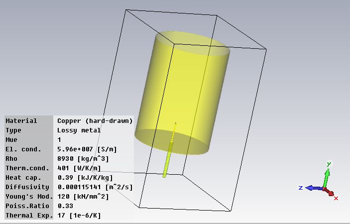
The project file for CST Microwave Studio can be found here:
http://www.tuks.nl/Spice/TM_01_Mode_Cantenna/TM_Mode_Cantenna_v1.cst
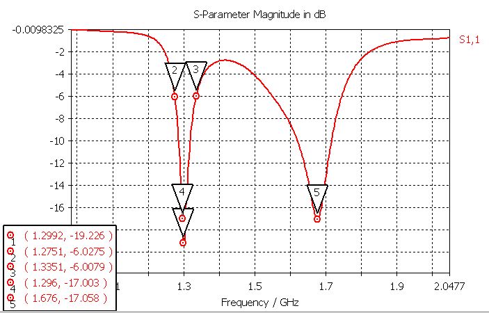
Then, one of the most important graphs, the S-Parameters:
http://www.antenna-theory.com/definitions/sparameters.php
Here's a handy page where you can convert the S-parameters into a/o VSWR and Reflection coefficient:
http://www.giangrandi.ch/electronics/anttool/swr.html
For a return loss of -17 dB, we get a VSWR of 1.33:1 or a reflection coefficient of 0.14.
For a return loss of -6 dB, which is the value used to determine the bandwidth of an antenna, we get a VSWR of 3:1 or a reflection coefficient of 0.50, which means that half the power sent to the antenna by the transmitter is reflected back to the transmitter. So, according to the simulation, this antenna should be usable between about 1275 and 1335 MHz.
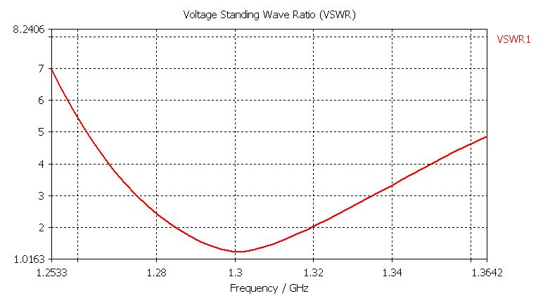
The VSWR plot:
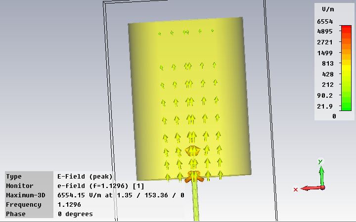
The E(lectric) field at 1296 MHz as seen from the side of the antenna. As you can see, it points nicely in the length direction of the antenna:
The H (magnetic) field at 1296 MHz as seen from the open end of the antenna. As you can see, it points nicely in circles:
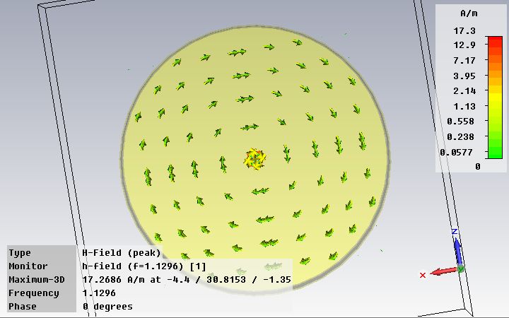
What we see is what we expect to see when a TM_01 mode wave is present in the waveguide and it shows that power is being transmitted based on the near-field calculations which should be realiable, so to me this is an encouraging result. Encouraging enough to try and make a pair of these to see what they do in practice. If Eric is right, then we should see a longitudinal wave being transmitted right in the length direction of the waveguide:
Originally Posted by jpolakow
[...]
Looks like I should have listened to Eric right from the beginning and should have started with a TM mode waveguide instead.
Either way, I learned a lot so far, even though I chose the hard way to do so.
Finally, the far field at 1296 MHz, which predicts that the antenna radiates the most energy sideways from the open end of the antenna:
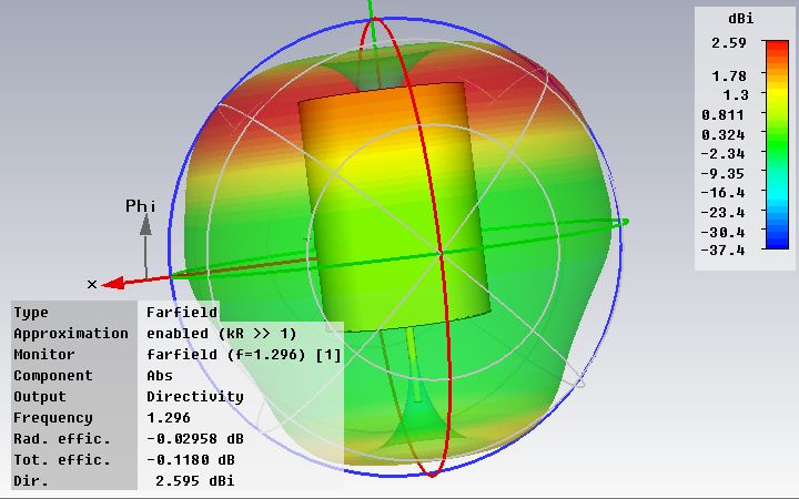
However, I don't trust the far field calculations of the simulator, because these do not account for longitudinal waves to exist.
73's!
Today, I made two antennas according to the new design. I scored two tin cans of exactly the right dimensions in my mother's kitchen
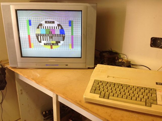
I made a setup with my old MSX computer as video signal generator, a small 23cm ATV transmitter, an old analog satellite receiver, a television set and a "satfinder" power meter. Of course, this is nothing like professional measuring equipment, but at least I can do some screening.
I did some experiments in my shack. First of all, I was able to transmit the test signal to the sat receiver and make it visible on the TV set, using pieces of about 5,7 cm wire as whip antennas. So, both the transmitter and the receiver work. The receiver even worked without antenna... Then I connected the power meter and played a bit with it. It worked as expected.
Then I connected one of the waveguide antennas to the transmitter and also got a nice picture on the TV set. It wasn't completely stable 100% of the time, but I can't seem to program the receiver with my replacement remote control. However, it's good enough for my purpose.
I played a bit with the wire antenna to try and get some idea about the radiation pattern. I also experimented with a small sphere antenna made of aluminum foil as replacement for the wire antenna. Finally, I played a bit with both waveguides connected, using the power meter.
The results were mixed. At some points, it seemed that a strong signal was present along the desired radiation direction, along the length of the waveguide, and sometimes it seemed like most power went sideways as the simulation predicted. So, no clear results but all in all not too bad.
However, I tested with a distance of about 2-3 meters using 75 Ohm coax cable (which is OK for the receiver which is 75 Ohm, but not for the transmitter which is 50 Ohm) and the transmitter nearby, so there may have been all kinds of reflections on the walls and wires in my shed, which make the measurements unreliable.
So, the next step will be to take some measurements outside in the garden over a distance of about 20-30m.
Now tomorrow is mother's day, so I don't think I will be able to do measurements tomorrow. We will have to save that for another day.
Yesterday, I did some experimenting with the two antennas in the garden over a distance of 25-30m.
I used my old MSX computer as a signal generator for feeding the 23cm ATV transmitter hooked up to one of the antennas:
And I used a Nokia Sat 1200S satellite receiver, hooked up to the other antenna at the other end of the garden. If anyone has some info on how to program this thing, I'd be grateful, btw.
It was pretty hard to receive anything and there did not appear to be a beam in the length direction of the antennas. It appeared as though the simulator was correct and most of the radiation went sideways.
Then I found out that the receiving antenna was hooked up to the wrong antenna input of the reciever.
Because I did not have an original remote control, I had to switch the receiver to a channel which happened to already be at the frequency of the transmitter. Now because the receiver has two antenna inputs, I did not notice that the channel I was using yesterday used the other input. I already noticed that my satfinder did not appear to get any power, but it did not cross my mind I may have been using the wrong input...
When I switched to the channel I used previously, I suddenly got a christal clear reception, such that it did not matter in any way how I was aiming the antennas.
So, I will have to reduce the transmission power before I can do any reasonable measurements. And I may also have to use 50 Ohm Coax instead of 75 Ohm between the transmitter and the antenna, since it may very well be that it is actually the coax cable acting as transmitter antenna.
In other words: it looks like most of the energy is transmitted as normal transverse waves, be it by the antenna or by the coax cable. It is unclear if any longitudinal waves are being transmitted. If at least a portion of the energy is radiated longitudinally this way, I can see if I can reduce the transverse transmission. If not, I'm back to square one.
So, I will first see what happens if I feed the transmitter with a lower voltage the next time I can do some experiments.
When looking for capacitive loads on antenna, I found an interesting patent which uses a (partial) sphere in an antenna structure:
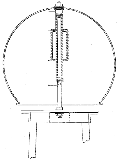
Related patents: http://www.tuks.nl/pdf/Patents/Brown_Nickle_Antennas/
Also found some interesting info on capacitive antennas: http://www.tuks.nl/pdf/Reference_Material/Capacitive_Antennas/
You bring forth many good points and questions. I think it is possible to transmit longitudinal waves between a transmitter and a receiver. Someone recently pointed me to some papers by the Erdmann brothers, which suggest they actually succeeded in doing this:
http://www.tuks.nl/pdf/Reference_Material/Fast_Light/
Another example of longitudinal waves is the famous dual slit experiment with light, whereby you get interference patterns. This experiment has been vastly misinterpreted and gave rise to the current quantum mechanics crackpot theory, whereby particles are supposed to be capable of existing at multiple places at the same time, etc. In reality, what happens of course, is the changing of propgation mode from "transverse" particle mode into longitudinal mode at the slits, which is what gives you the interference pattern.
The reflection part is a much more difficult question to answer. It may very well br that longitudinal waves will reflect nicely on a dish and a planet. It may also be that the reflected wave is a "transverse" wave. And it may also be that the waves simply pass trough the dish/planet and hardly reflect. I suspect the waves will reflect though, because in water, for example, longitudinal waves reflect the same way as transverse waves to a wall, etc.
Originally Posted by Robert-in-the-UK
That is actually the reason I came up with my first idea of partial concentric spheres:
[QUOTE=lamare;166696]Hi all,
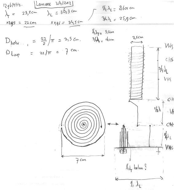
I made a new drawing of the lamare longitudinal dipole antenna, with dimensions for 1296 MHz:
[CENTER][IMG][/IMG][/CENTER]
Updated spreadsheet with my calculations: [url]http://www.tuks.nl/Spice/Lamare_dipole_calc.xls[/url]
Oh yeah, I almost forgot. Aluminum and copper can be soldered together:
[url=http://users.monash.edu.au/~ralphk/solder-aluminium.html]solder-aluminium[/url][/QUOTE]
[QUOTE=lamare;167938]Based on the last update in the above post explaining we can choose any odd multiple of 1/15th of the circumference of the big sphere, we can also opt for 5/15th, which would be 1/3d.
Therefore version 4 of the design:
[url]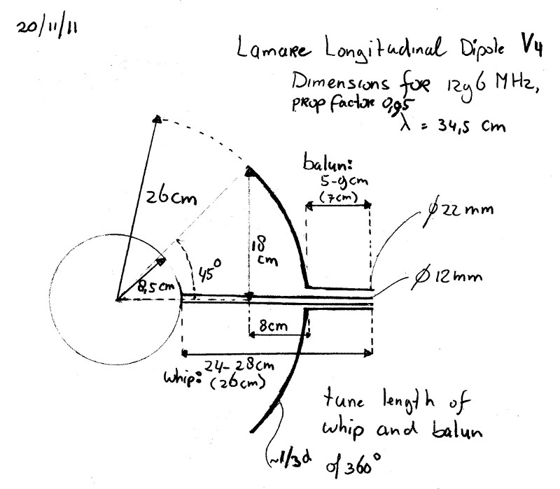 [/url]
Grrrrr.
How much is 360 divided by 3??
Right, 120...
- wall
- :wall: :wall:
Yep, that's another number than 90....
So, back to the drawing board....
[B]Update[/B]: Here's version 5:
[CENTER][IMG][/IMG][/CENTER]
With a high-res version for printing, etc:
[B]Update 2[/B]:
I have done some calculations on the surface area of these so called "spherical caps", which you can find in my spreadsheet:
[url]http://www.tuks.nl/Spice/Lamare_dipole_calc.xls[/url]
It turns out that a cap for 1/5th has a surface area of about 86% of the surface of the small sphere, while a 1/3 cap will give avout 225% of the surface of the small sphere.
So, I think we'll go for version 3. Easier to make, and more in balance with respect to surface area's (== self capacitance and/or charge density):
[url]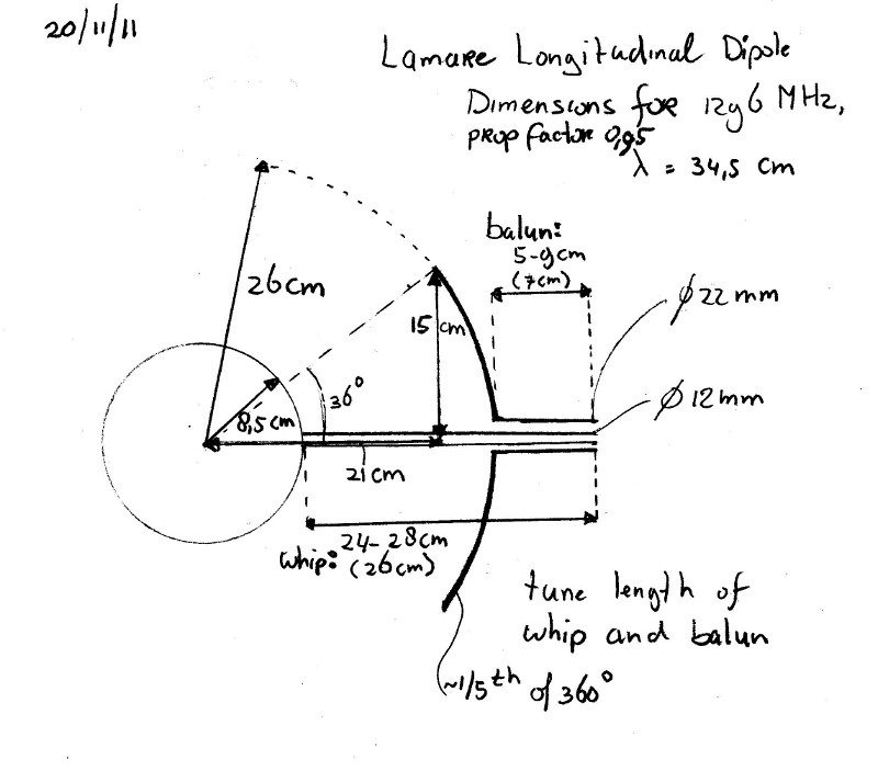 [/url]
And that's it for today...[/QUOTE]
I never went further with those ideas, because they are pretty hard to construct.
Notes
�Het meeste van wat Lammertink schrijft lijkt me onzin (longitudinale em golven zijn nooit aangetoond) maar ik weet niet voldoende van EM-theorie.�
http://en.wikipedia.org/wiki/Laser
�Some applications of lasers depend on a beam whose output power is constant over time. Such a laser is known as continuous wave (CW). Many types of lasers can be made to operate in continuous wave mode to satisfy such an application. Many of these lasers actually lase in several longitudinal modes at the same time, and beats between the slightly different optical frequencies of those oscillations will in fact produce amplitude variations on time scales shorter than the round-trip time (the reciprocal of the frequency spacing between modes), typically a few nanoseconds or less.�
http://en.wikipedia.org/wiki/Longitudinal_mode
�A longitudinal mode of a resonant cavity is a particular standing wave pattern formed by waves confined in the cavity. The longitudinal modes correspond to the wavelengths of the wave which are reinforced by constructive interference after many reflections from the cavity�s reflecting surfaces. All other wavelengths are suppressed by destructive interference. A longitudinal mode pattern has its nodes located axially along the length of the cavity. Transverse modes, with nodes located perpendicular to the axis of the cavity, may also exist. [...] A common example of longitudinal modes are the light wavelengths produced by a laser. In the simplest case, the laser�s optical cavity is formed by two opposed plane (flat) mirrors surrounding the gain medium (a plane-parallel or Fabry�P�rot cavity). The allowed modes of the cavity are those where the mirror separation distance L is equal to an exact multiple of half the wavelength, λ.�
Ik zou toch zweren dat ik hier lees dat lasers met longitudinale golven werken en dat transversale modes wellicht ook zouden kunnen bestaan� Hmmm.
Voor wat betreft het nooit aangetoond zijn van longitudinale EM golven: dat is absoluut niet waar. Longitudinale EM golven zijn een algemeen bekend verschijnsel in radio engineering.
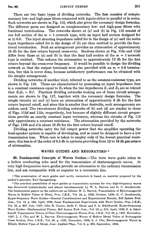
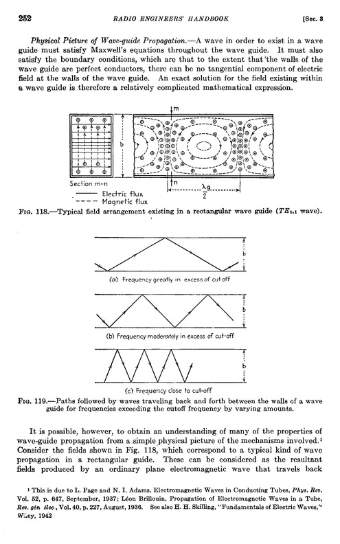
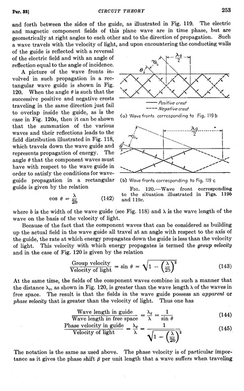
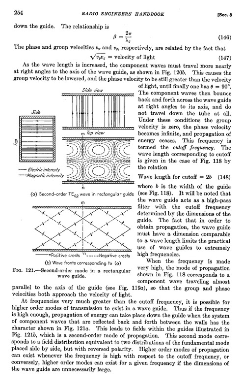
Eric Dollard poste enige tijd geleden een bladzijde uit het radio engineers handbook over golfpijpen:

De beide TM modes die je daarin ziet zijn dus longitudinaal electrisch, transversaal magnetisch.
En als je dan even het ontwerp van een laser voor de geest haalt, dan heb je in feite daarmee ook een golfpijp, maar dan voor optische frequenties.
http://en.wikipedia.org/wiki/Laser
�The optical resonator is sometimes referred to as an �optical cavity�, but this is a misnomer: lasers use open resonators as opposed to the literal cavity that would be employed at microwave frequencies in a maser. The resonator typically consists of two mirrors between which a coherent beam of light travels in both directions, reflecting back on itself so that an average photon will pass through the gain medium repeatedly before it is emitted from the output aperture or lost to diffraction or absorption.�
Nu heb je bij een EM golfpijp dus een metalen wand, waarbij de aanwezigheid van een wisselend E-veld wervelstromen geinduceerd worden in de pijpwand en die vervolgens weer een magneetveld tot gevolg hebben. Maar bij een laser heb je alleen twee spiegels en dus geen pijpwand die middels inductie een magneetveld introduceert.
Kortom: longitudinale EM golven zijn wel degelijk aangetoond zonder dat de propagatie plaats vindt middels beweging van ladingsdragers, zij het dat dit in een golfpijp een TM mode is en dus geen zuivere �Tesla� LD golf. Het afwezig zijn van een metalen wand in een laser met daarbij de verwijzingen naar �longitudinale� mode wijzen er dan ook wel degelijk op dat we bij een laser te maken hebben met een zuivere longitudinale dielectrische golf, zo�n Tesla golf.
En als die inderdaad met pi/2 keer c propageren en daar is geen rekening mee gehouden bij optisch onderzoek, dan zou je verwachten dat er ergens een anomaliteit te vinden is die e.e.a. zou kunnen bevestigen.
So far, I have been unable to construct suitable antennas, but it should be possible to do so. In the event you or any of your group members were to make a longitudinal antenna for the 23cm band or higher, we have a very nice dish antenna available for such an experiment:
http://en.wikipedia.org/wiki/Dwingeloo_Radio_Observatory
:)
I have gathered quite a lot of information about the subject, linked from the thread on EF. And if someone would make longitudinal antennas suitable to mount on the dish, we could finally prove Einstein's relativity theory to be wrong, because longitidinal dielectric waves propagate at a speed of sqrt(3) times c, and are NOT electromagnetic in nature.
http://www.tuks.nl/wiki/index.php/Main/Ruins96YearsEinsteinRelativity
Perhaps the most concrete design I found which could be built upon is the design by the Erdmann brothers, which would have to be scaled down for the 23cm band:
Some more referenence material on "faster than light" phenomena: http://www.tuks.nl/pdf/Reference_Material/Fast_Light/
This one is from "nature":
This makes clear that it is well accepted that faster than light phenomena are possible, indeed. What is not accepted is that these are actually caused by longitidinal electro"static" wave phenomena, which are sound-like pressure waves propagating trough the aether which do NOT have a magnetic component, as EM waves do.
Note that they manage to confuse "entrance" and "exit" interface to suggest that a resulting signal with a negative group velocity actualle exits the material before it enters the material:
"When qo is within such a region, ng can be less than one and can even become negative when the anomalous dispersion is large. This results in �fast light�, for which it is possible that the peak of a light pulse may exit the optical material before it passes through the entrance face."
This is of course total rubbish. A signal with a negative group velocity can only be caused by the result of some kind of heterodyning signals, which must first propagate trough the fiber, before a resulting "group" signal in the other direction can occur.
Either way, perhaps you or some of your group members are interested in doing some fundamental research in the area of the propagation of longitudinal dielectric waves and can build some antennas for that. It would be no problem to mount an antenna for the 23cm band or higher on the Dwingeloo dish and a succesfull moonbounce would definitely rock the science community all over.