Problem
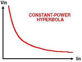
Failure of switching-mode power supply at low input voltage. Figure 1 shows the characteristics of a constant-power device, such as a switching-mode power supply, in the input V-I plane.

Figure 1: Constant Power Characteristic
As input voltage increases, input current decreases. Conversely, as the input voltage approaches zero, the input current approaches infinity. These high input currents at low voltage can damage components. Usually at highest risk are the semiconductor switches in switching-mode power supplies, which may be driven well outside their safe-operating region.
The problem often occurs at turn-on, when the source voltage starts at zero and then increases to the desired operating voltage. Failure can also occur at turnoff but is not found until an attempt is made to turn the supply on again. Then the failure is usually classified as a turn-on failure - masking the real cause of the failure and complicating trouble-shooting.
A common mistake in lab checkout of prototype designs, before protection is added, is to start with zero voltage and slowly bring the voltage up. Rather than minimizing stress, this can apply maximum current stress to the design causing failure.
Relevance
Any switching-mode power supply or other constant-power device operating at low line without inherent or designed-in protection. If the device or circuit naturally inhibits operation at low input voltage, the problem may be masked, but the inherent starting voltage may not be satisfactory under worse case conditions. PWM controllers often inhibit voltage at low line, but this operation should be checked under worse case conditions.
Solvability
Inhibit operation at low input voltages. The normal solution is to add a circuit that prevents operation until an input voltage is reached that meets the circuit specification. This circuit usually requires hysteresis to prevent on/off oscillation near the sense point for slowly varying or non-monotonic input voltage. Soft start circuits are often added to further reduce the input current stress.
Solution
Once the problem is understood, the solution is usually straight forward.
- Select the turn-on voltage for the power supply
- design a sense circuit for this voltage with hysteresis
- use the circuit to inhibit turn-on until the proper voltages are reached
- add soft start to minimize the load transient at turn-on
- and then by means of simulation and lab measurements, check the transient stress on components during turn-on and turn-off, especially the V-I trajectories of semiconductor switches in relation to their safe-operating area
Personal Anecdote
I learned this the hard way, as have many others, by burning out power transistors by slowing bringing up the input voltage on a switching-mode power supply breadboard. It took me a while to realize what was happening and to get into the habit of applying voltage as a step function until all protection circuitry was in place. Learning this used to be a common initiation rite for those designing switching-mode power supplies for the first time. Now PWM controller IC's and cycle-by-cycle protection of the power transistors in some forms of current-mode control have masked the problem so some designers are barely aware of the problem. However, if you are interested in field reliability, you should carefully check the turn-on / turn-off transient stress and add additional protection circuitry if needed.
On the Web
I have not found any information yet about this problem on the web.
References
A 1978 PESC paper by Aron Levy provides additional information. Other topics in this hypertext provide additional insight into the problem and its solution, including Latchup of Constant Power Load With Current Limited Source and Solar-Array Power System Battery Lockup.