Problem
The output voltage overshoots when the load is removed or a short clears. When the load is remove from a switching mode power supply with a LC low-pass output filter, the only thing the control loop can do is stop the switching action so no more energy is taken from the source. The energy that is stored in the output filter inductor is dumped into the output capacitor causing a voltage overshoot.
The magnitude of the overshoot is the vector sum of two orthogonal voltages, the output voltage before the load is removed and the current through the inductor times the characteristic impedance of the output filter, Zo = (L/C)^1/2. This can be derived from conservation of energy considerations.
The initial energy, Ei, is:
Ei = 1/2*(L*Ii^2 + C*Vi^2)
The final energy, Ef, is:
Ef = 1/2*(L*If^2 = C*Vf^2)
The two energies are equal when the load is removed, since the load is no longer taking energy from the system. Equating the two energies, substituting zero current for the final inductor current, then the solution for the final voltage Vf is:
Vf = (Vi^2 + (Ii*Zo)^2)^1/2
This is the orthogonal vector sum of the output voltage and the load current times the characteristic impedance and is illustrated in Figure 1.
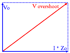
Figure 1: Overshoot Voltage as Vector Sum
The problem becomes worse if the current in the inductor is established by a short circuit on the output and the short circuit clears. In this case, the initial voltage is zero (short circuit) and the overshoot is I*Zo, where I can be very large, resulting in a ruinous overshoot.
Relevance
Applies to all switching mode power supplies with output filters using inductors. The problem is illustrated with an LC filter of the type used on the output of the simple buck converter. The general problem identification process is to determine the energy that is stored in circuit inductance and capacitance under normal and abnormal conditions and make sure it causes no damage when released under normal and abnormal conditions. Two such conditions are load shedding and clearing of a shorted output.
Solvability
Make overshoot a major selection criteria in the design of the output filter and in the selection of short-circuit or overvoltage protection.
Overshoot can be minimized by minimizing the filter characteristic impedance, Zo, by decreasing inductance or increasing capacitance or both.
Some overcurrent protection circuits limit the maximum current that can flow in the output filter inductor. Others do not. For overshoot control purposes, the former are preferred.
Independent overvoltage protection circuits should be considered mandatory until careful analysis of operation in normal and abnormal operation indicate they can be eliminated or modified to the semi-independent variety.
Solution
One simple algorithm for the first cut design of an output filter is to select the inductor to limit the peak-to-peak inductor ripple current to 10% of the full load current and to select the capacitor to limit overshoot to the absolute maximum voltage rating of the load circuits. (Even then, overvoltage protection is recommended.) This keeps component stresses near static stresses and places the discontinuous current boundary at 5% of full load.
The ripple voltage across the capacitor (neglecting parasitic inductance) is a vector sum of voltage components across the capacitor's resistance and capacitance. The capacitance selected for overshoot is almost always enough so the output ripple is primarily due to the ESR (Equivalent Series Resistance) of the capacitor.
This then provides a starting point for optimizing the filter design, taking in all the other design criteria that has to be met (i.e. overshoot, ripple, attenuation of input noise, bandwidth, component stress, discontinuous current boundary, stability, Middlebrook criteria, and interaction with other reflected filters).
Notice this is much different then the algorithm used in most text books and application notes that use break frequency and output ripple to determine output filter values. The main thing to remember is that either algorithm is just a starting point to get to an optimum filter (one that meets performance criteria in the smallest size, weight, or cost, or acceptable combination).
The algorithm I mostly use is more complex than either of these and starts with the converter power level, conducted EMI specification, and a mockup of physical components. These are used to design the input filter, and then design the output filter to "fit" the reflected input filter with acceptable overshoot. Mockups of the package and components are continually used. Then the optimization starts with this output filter, which may affect the design of the input filter. By using impedance paper to do the preliminary design, this goes very rapidly. By using physical mockups, there are no packaging or manufacturing surprises, important because filters are a major contributor to the size and weight of a switching-mode power supply.
Personal Anecdote
During the 1970's, a major semiconductor vendor released a widely distributed application note on the design a switching-mode power supply. As I recall, it was for a 5V, 12A, forward converter. Their recommended output filter resulted in a 15V overshoot on the 5V output when the 12A load was removed. No overvoltage protection was shown. This degree of overshoot would destroy most logic circuits for which the supply was intended, or worse, severely degrade their reliability without destroying them.
In this time period, few design activities were familiar with switching-mode power supply design and the application-note design was widely copied into system proposals. Instead of indicating the design activity was competent in this type design, it indicated the opposite and lost the vendor points during proposal evaluation.
Virtually every experienced switching-mode power supply designer has heard of some horror story associated with overshoot. The worst I heard was during the 1960's when a designer of commercial main-frame computers was working on a new prototype, which was powered by 60 Hertz saturable reactor switcher feeding a huge LC filter. A short occurred in the load establishing a large current in the inductor, and then the short cleared. The resulting overshoot destroyed all the logic circuits. It cost the program over a million (1960's) dollars. Needless to say, independent overvoltage protection became mandatory.
Because of many such horror stories, for many years you never saw a power supply without overvoltage protection. Now you do, indicating the lesson will have to be relearned the hard way.
Finally, it is important to note that it is impractical to meet all requirements in some designs. More than once I have had to relax overshoot somewhat and rely on the overvoltage protections circuit for abnormal events.
On the Web
I have found nothing on the web yet.
References
There are no papers referenced in this solution. Almost any text covers the simple part. There are some papers on optimization that will eventually be included in this hypertext. I know of no paper or text that puts it all together.